What combines the strength of steel, the efficiency of modern plastics, and the safety standards the industry demands? DuraPlas TuffStand pipe stands.
Industry tests show promise for non-welded repair of oil and gas pipeline circumferential cracks.
A recent joint industry project led by C-FER Technologies has shown promising results for using Petrosleeve, a non-intrusive repair method, to arrest circumferential crack growth in pipelines.
The multi-phase JIP is testing a range of non-welded repair technologies to determine if they are a safe and cost-effective alternative to repair circumferential cracks compared with traditional methods.
At the 2025 Pipeline Pigging and Integrity Management (PPIM) Conference, PeroSleeve’s Bob Smyth reported on Petrosleeve’s results within the JIP, producing a paper titled Interim Results from the JIP Evaluation of Repair Technologies for Circumferential Cracks on Pipelines of the Steel Compression Reinforcement Sleeve; Repair F (PetroSleeve). This article is a summary of his presentation.
Why research for circumferential crack non-welding repair matters
Traditional repair methods for circumferential cracks typically involve removing the damaged section of pipe or installing a welded Type B sleeve. But both come with tradeoffs. Cutting out pipe can be expensive and disrupt operations, while in-service welding adds complexity and additional risks.
Non-welding solutions offer a fast installation option with less equipment required than metal sleeves, plus the flexibility to repair pipe with non-uniform geometries or where in-service welding may not be feasible.
To explore non-intrusive options, the JIP brought together stakeholders to test six non-intrusive repair technologies. One of them — referred to as “Repair F” in the study — was Petrosleeve.
What is Petrosleeve?
Petrosleeve offers a simple, non-intrusive alternative to traditional forms of circumferential crack repair.
It’s a two-part steel sleeve that clamps around the pipe and is joined by external sidebars – with no welding to the host pipe required. During installation, the pipeline is slightly pressurised, putting the pipe into compression and the sleeve into tension. This creates a tight mechanical bond that helps prevent crack propagation.
Before installation, key parameters like wall thickness, internal pressure, flow rate, and pipe temperature are used with proprietary software to tailor the installation of the repair for each site.
How the circumferential crack non-welding repair methods were tested
C-FER’s JIP evaluated six non-intrusive repair options through a rigorous four-phase program, involving performance tests under pressurised conditions on X52-grade pipe.
The non-intrusive methods tested included wet lay-up, composite fabric, preformed composite coil, steel sleeve, or bolt-on repair sleeve/collar.
Repair F (Petrosleeve) demonstrated robust structural performance across all phases.
Phase 1: structural strength
The repair systems were installed on three sections of 24-inch X52 pipe pressurised to 785 psi (5,400 kPa) to mimic real pipeline conditions.
Each system was subjected to various non-destructive tensile testing situations to compare axial stiffness. This included pressure cycling before being pressurised to 1,170 psi (8,060 kPa) with axial tension applied until a section of the control pipe reached plastic collapse.
Following Phase 1, only three repair methods were selected to participate in further testing. Repair F was deemed acceptable for further testing.
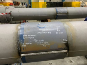
Petrosleeve installed on the pipe specimens used during Phase 1 of the JIP.
Phase 2: installation pressure effects
Phase 2 explored how internal pressure during installation affects repair performance via tests on seven 12-inch vessels pressurised at 30 per cent, 50 per cent and 70 per cent of specified minimum yield strength (SMYS). The vessels were put under tension, and at 72 per cent SMYS, put under tension until failure.
Results showed consistent behavior of Repair F across various pressures, maintaining favorable stiffness ratios, load sharing and strain compatibility with the host pipe. Following Phase 2, Repair F was one of two repair methods deemed acceptable for further testing.
Phase 3: real crack testing
This critical phase introduced simulated circumferential cracks — up to 80 per cent through-wall depth — to evaluate how the repair systems performed under extreme conditions. Each repair system completed the destructive tensile test under varying pressures until they failed.
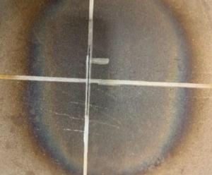
Photo illustrating the 80 per cent simulated crack.
Each vessel was pressurised to 62.5 per cent SMYS to confirm the crack wouldn’t rupture during the installation of each repair method. The systems were then installed at 50 per cent SMYS and exposed to pressure variances. At 72 per cent SMYS (1,482 psi/10,200 kPa), the vessels were put under tension until failure occurred by increasing tension until the host pipe entered the plastic range and the crack opened.
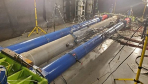
During Phase 3 tensioning.
Repair F effectively contained the defect under normal operational pressures. The pipe only failed when reaching the plastic range under high tension at 560 Kip (560,000 lb-force) — a level of strain unlikely outside of severe events like landslides or earthquakes. This indicated good containment up to extreme loading.
Phase 4: long-term durability (ongoing)
Phase 4 assesses long-term performance under cyclic pressure. In this test, the participating repair systems were installed on three vessels with an 80 per cent simulated circumferential crack before being put under tension and load to simulate field conditions.
The Repair F Petrosleeve specimens tested in this phase completed 1,000 hours without leaking.
What the interim results show
So far, key observations from the study include evidence of compressive pre-stress between Petrosleeve and the pipe, with crack containment maintained until significant yielding occurs in the parent metal.
Petrosleeve’s results in Phase 3 showed that the repair method only failed when the steel was in the plastic range, with the steel at the edge of the sleeve yielding, reducing the circumference of the pipe and breaking the compressive bond between the pipe and sleeve. This exposed the crack to the tensile force, stretched the steel, and the crack opened.
This suggests Repair F could reliably contain circumferential flaws under normal operational stresses, with failure only likely in rare, high-strain events, such as major geohazards like landslides or earthquakes.
A potential reliable alternative to traditional methods for repairing pipeline circumferential cracks
While testing is ongoing, the early results are promising. Repair F (Petrosleeve) has demonstrated credible performance across short-term mechanical and pressure testing. Ongoing long-term testing will further validate its field viability as a non-welded option for circumferential crack repair.
Petrosleeve could offer pipeline operators a non-intrusive, safe, effective repair method for circumferential cracks — without shutting down operations or risking the hazards of hot welding.
The early JIP results indicate that it can contain significant crack defects and maintain integrity until extremely high strain levels are reached — beyond what most operational scenarios would impose.
For more information on Petrosleeve, contact its exclusive agent for Oceania: Tremco Pipeline Equipment a sales@tremcopipelineequipment.com.au
Sawyer Manufacturing Company’s pipeline rim clamps provide an easy solution for tough pipe reforming jobs. Watch Sawyer’s step-by-step instructions on how to use the clamp for maximum accuracy and minimal downtime.
Suitable for pipe sizes from 4 inches to 72 inches, Sawyer’s manual lineup Rim Clamp is designed for use on out-of-round pipes that require a high level of alignment accuracy. The Rim Clamp can reform 45,000 PSI tensile strength pipe up to Schedule 80, with out-of-round conditions of up to 2 inches (51 mm) depending on wall thickness. For larger jobs, Sawyer’s heftier Ultra Rim Clamp can provide the same benefits.
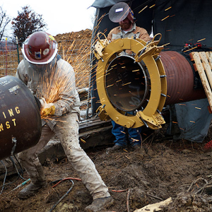
The Rim Clamp being used in the field. Image courtesy of Sawyer Manufacturing Company.
Why choose the Sawyer Rim Clamp?
Sawyer Manufacturing Company has been designing and manufacturing pipeline and welding equipment in the USA since 1948, and has a long-standing 20+ year partnership with Tremco Pipeline Equipment to supply its equipment to the Oceania region.
Sawyer’s rim clamps:
- High reforming capacity: handles up to X45 Schedule 80 pipe with tensile strength up to 45,000 PSI and up to 2″ out‑of‑round conditions, depending on wall thickness
- Rigid shell design: offers a robust external alignment solution, preferred by users who need consistent accuracy and reliability over flexible chain clamps
- Efficient setup: The jackscrew setting gauge speeds setup and ensures repeatable precision.
- Safe and stable: heavy‑duty galvanised construction, pivoting pads on jackscrews, and a secure latch mechanism provide stability and safety in field conditions
- Thoughtful tools: each rim clamp also comes with a set of tools for operation, including a torque wrench, speed handle, and socket for reliable pressure control and efficient operation.
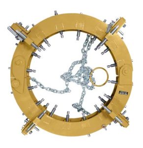
The Rim Clamp. Image courtesy of Sawyer Manufacturing Company.
How do pipeline rim clamps work?
The rim clamps feature multiple heavy duty, galvanised jackscrews, which give the user the ability to apply precise reforming pressure on specific areas of pipe. The specialised torque wrench supplied with the clamp furthers this capability by allowing the user to set the exact torque required for the reforming application, saving time and effort by setting the perimeter of the jackscrews before the external line up clamp is placed on the pipe. The unique jackscrews on Ultra RIM Clamps have trapezoidal thread, which makes them stronger than conventional jackscrews and able to assert more reforming pressure on the pipe.
Hinged flip-up jackbars allow for simple pipe mating, and also ensure the clamp can be used for applications requiring 100 per cent welding and/or grinding without removing the pipe clamp. Each jackbar comes with a pivot pad, allowing this pipeline welding clamp to be used on coated or uneven pipe surfaces.
A step by step guide to using the Sawyer Rim Clamp
Watch this short video for a quick explanation of how to use Sawyer’s Rim Clamp.
The setup process for the Rim Clamp is engineered to save time and protect equipment:
- Unlock and position the clamp: Release the clamp’s locking mechanism by pulling on its chain-operated hook. Once open, lift the clamp onto the pipe. Smaller 4-12 inch units can be placed manually, while larger sizes require mechanical lifting using the clamp’s built-in lifting chain.
- Center and preset the jackscrews: Before placing the clamp around the pipe, loosen all reforming jackscrews except for the top two. Use the jackscrew setting gauge (provided) to preset these top screws to the approximate pipe radius. This prevents thread damage during installation and ensures the clamp sits true from the start.
- Securing the Clamp: Lower the clamp onto the pipe so that the adjustable jackbars extend approximately 2 inches beyond the pipe ends. As the clamp closes, the locking hook should auto‑latch. If it doesn’t, push the two sides inward until latched securely.
- Align and level the pipe: Use the reforming jackscrews to center the clamp within ±1 inch. Then adjust the stable jackbars until the clamp is perfectly perpendicular to the pipe axis. Slight tweaks to the reforming screws may be required during this step.
- Fitting a secondary pipe or fitting: To align a secondary pipe or fitting, remove the latch pins on the top adjustable jackbars and swing them upward and clear of the joint. This allows full access for alignment and welding prep before reforming pressure is applied.
- Reforming the pipe: Once the two are roughly aligned, begin tightening only the reforming jackscrews over the pipe’s high‑spot and directly opposite (180° apart), working in sequences of three jackscrews. Don’t use all the jackscrews. Avoid overtightening—only apply enough pressure to reform the pipe incrementally. A back-and-forth tightening process (tightening and relaxing) may be needed to bring the pipe back to true round without overstressing the material.
- Release the jackscrews: Once the pipe has been reformed, loosen the jackscrews over the high spot, working in a sequence of three jackscrews. It will be necessary to reduce the pressure of some jackscrews as you tighten others. It may be necessary to repeat this procedure several times.
Take on the toughest pipeline reforming jobs
From placement to reforming, the Sawyer Rim Clamp provides a systematic way to correct ovality and achieve precise line‑up for pipeline welding. Its durable frame, calibrated jackscrews, and thoughtfully designed tools—like the setting gauge and torque wrench—make it a trusted choice for jobs where accuracy is critical.
Not sure the Rim Clamp is the right pipe clamp for you?
Sawyer Manufacturing’s line of pipe-to-pipe fit-up equipment provides a good range of durable, simple, easy-to-use and accurate pipe clamps to meet different needs. Find the right pipe clamp for your specific needs here.
To learn more about Sawyer’s rim clamps and other products, contact the Tremco Pipeline Equipment team at sales@tremcopipeline.com.au or call 07 3344 1066.