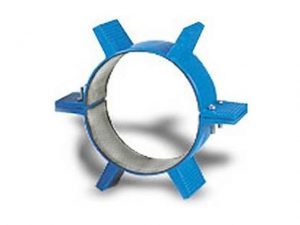
Maloney Model 90 Casing Insulators
Maloney Model 90
Model 90 Casing Insulators are manufactured from virgin high density polyethylene (HDPE Type II).
Insulators are molded in two sections, designed for simplified field installation, and use threaded inserts requiring only a screwdriver for assembly. A rubberized liner is factory-installed to prevent slippage between the insulator and the pipe. All hardware is stainless steel to resist corrosion. The Insulators exhibit low friction and the high abrasion resistance allowing carrier pipes to be more easily pulled through the casing.
The Model 90 is specifically designed to raise the belled portion of cast iron and PVC pipe above the inside surface of the casing pipe. In the event of a nonstandard configuration, molded “cutting guides” on the sides of each fin permit easy manually trimming fins to a uniform height.
Insulator Spacing:
The Model 90 Casing Insulator is designed to carry the filled weight of the pipeline without deformation of the support fins. For proper operation, it is recommended that insulators be installed 1 foot from each casing end, 1 foot from each side of a pipe joint, and with 4 to 6 feet spacing on the pipe barrel. Actual spacing may vary depending on local regulations and design specifications.
Waterworks Casing Insulator Physical Properties
| Dielectric Strength | |
| (ASTM D-149 | 400 • 500 volts/mil |
| Compressive Strength | |
| (ASTM D-695) | 3200 psi |
| Flexural Yield | |
| (ASTM D-790) | 1000 psi |
| Tensile Strength | |
| ASTM D-638, | 31 0 – 5500 psi |
| Impact Strength | |
| (ASTM D-256) | 4 ft lbs/in of notch |
| Water Absorption | |
| (ASTM D-570) | <.01% |
| Maximum Continuous | |
| Operating Temperature | 225°F |
Dimensions and Specifications
| Carrier Size | Minimum Casing Size | Diameter Over Runners | Number of Runners | Number of Segments | Width |
| 4″ | 10″ | 9-1/8″ | 6 | 2 | 4″ |
| 6″ | 12″ | 10-15/16″ | 6 | 2 | 4″ |
| 8″ | 16″ | 14-7/16″ | 6 | 2 | 4″ |
| 10″ | 18″ | 16-1/4″ | 6 | 2 | 4″ |
| 12″ | 20″ | 18-1/8″ | 6 | 2 | 4″ |

